Intersection Buffers

Image Source: Google Earth – MN 95, Minnesota
DEFINITION AND DESCRIPTION
Intersection buffer treatments can be applied at rural, high-speed intersections with side-street stop control. They narrow the mainline approach intersections by adding a striped buffer area that includes centerline rumble strips. This narrowing is intended to encourage drivers to reduce speed as they approach the intersection. The striped buffer area also enhances separation between opposing traffic and increases the visibility of the intersection. Following installations in Minnesota, fatal and injury collisions decreased by 22% (Moreland et al., 2024).
Implementation Categories
| Area(s) | Design & Geometrics, Traffic Operations & Operations and Maintenance |
| Safety Category | 2 |

CONSIDERATIONS
- At intersections with left-turn lanes, the buffer should be placed between the through lane and the left-turn lane to provide a positive offset.
- The maximum through lane width at the intersection is 10 ft. This application is not appropriate for roadways with lane widths less than 11 ft.
- See MUTCD Part 3 – Markings for information on pavement markings.
- If noise from the rumble strips are a concern, consider sinusoidal rumble strips. Details for these applications are on HSIP’s Project Development Resources website.
APPLICATION
- May be applied at rural, two-lane undivided, side-street, stop-controlled intersections.
- When turn lanes are not present begin the taper to narrow the lane approximately 300 ft prior to the intersection. The taper rate should be 1:posted speed.
- When turn lanes are present, the lane width taper should begin at the start of the turn-lane taper. Turn-lane widths are not reduced.
- The buffer is typically 4 ft, but may be 2 ft if existing through lane widths are narrower than 12 ft.
- Lane widths are typically narrowed to 10 ft.
- Rumble strips are applied on the approach side of the buffer and between the through and turning lanes.
- Can be included in resurfacing projects.
example

Image Source: Minnesota DOT
REFERENCES AND RESOURCES
Moreland, M., Leuer, D., DeVoe, E., & Mwangi, R. (2024). Traffic Safety Evaluation of Lane Constrictor Intersections in Minnesota (Tech. Rep. No. 2024-03). Minnesota Department of Transportation, Office of Traffic Engineering. Retrieved from https://rosap.ntl.bts.gov/view/dot/73832
CONTACT:
Jill Asher
Research Engineer
jill.asher@uky.edu


Speed Tables and Raised Crosswalks

DEFINITION AND DESCRIPTION
A speed table is a raised area installed across the roadway to limit vehicle speeds. It extends across the roadway and has a flat top sufficiently long (typically, 10 feet) to accommodate the entire wheelbase of most passenger vehicles. Compared to speed humps, their extended longitudinal depth in the direction of travel enables faster vehicle operating speeds while preserving motorist comfort and safety. Raised crosswalks may be placed on top of speed tables.
Three field studies of 27 speed tables measured crash reductions of 36% – 64%. Six field studies of 98 speed tables measured reductions in 85th percentile speeds of 4 mph – 11 mph (FHWA, Engineering Speed Management Countermeasures: A Desktop Reference of Potential Effectiveness in Reducing Crashes, July 2014). Raised crosswalks can reduce pedestrian crashes by up to 45% (FHWA, Countermeasure Tech Sheet, June 2018).
Implementation Categories
| Area(s) | Design & Geometrics, HSIP, Operations & Maintenance |
| Safety Category | 2 |

CONSIDERATIONS
- Do not install on sharp curves; ITE Guidelines for the Design and Application of Speed Humps recommends a minimum horizontal curve radius of 300 feet.
- Speed tables may be used at intersections or mid-block crossings as raised crosswalks.
- If used at intersections, consider the impact on required intersection sight distance since vehicles turning across the raised crosswalk from a stopped position will accelerate more slowly to enter the intersection.
- Drivers turning across a raised crosswalk from an uncontrolled approach will require more intersection sight distance since they will be required to find an adequate gap in traffic and then reduce their speed to navigate the vertical deflection.
- Consider drainage in design.
- Generally, not appropriate for transit routes, primary emergency vehicle routes, or along routes that provide primary access to commercial or industrial sites (freight).
- ITE Guidelines for the Design and Application of Speed Humps recommends consideration only on a street with a grade of 8% or less.
- On roadways without curbing, delineator posts or signs may be used to discourage motorists from driving around the hump.
- Speed tables can be used on roadways with bicycle lanes.
- Raised pedestrian crossings are one of the four treatments that fulfill the PROWAG requirement (R306.4.2) for multilane crossings at roundabouts.
APPLICATION
- May be appropriate for local and collector streets with low operating speeds and an AADT < 9,000 and on arterials in certain circumstances.
- Typically, speed tables are elevated approximately 3 inches, while speed tables with crosswalks range from 3 inches to the height of the sidewalk. Transition slopes range from approximately 12:1 to 25:1. Longer approaches and plateaus are better able to accommodate large vehicles but may also result in higher vehicle speeds.
- ITE Guidelines for the Design and Application of Speed Humps recommends spacing of 260 feet – 500 feet between successive speed bumps to maintain 85th percentile operating speeds of 25 mph – 30 mph. Spacing can be adjusted to achieve speeds closer to the target speed.
- Install signs upstream of the installation to warn drivers (MUTCD W17-1). Where a speed table is designated as a pedestrian crossing, a pedestrian sign may be used instead. See Sections 29 and 3B.30 of the MUTCD for information on using markings at and in advance of speed tables.
example
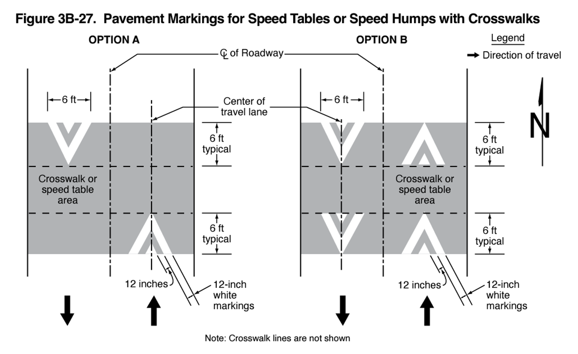
Source: MUTCD 11th Edition
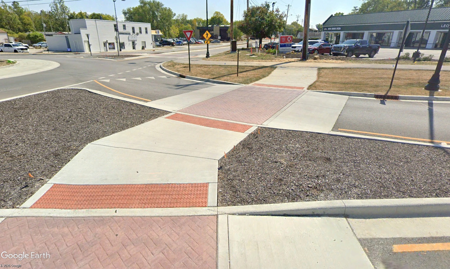
Image Source: Google Earth, Carmel, IN
complementary SSA Strategies
- Medians and Pedestrian Refuge Islands
- Supplemental In-Lane Pavement Markings
REFERENCES AND RESOURCES
Federal Highway Administration. Manual on Uniform Traffic Control Devices for Streets and Highways (MUTCD), Federal Highway Administration, U.S. Department of Transportation, Washington DC, 2023. https://mutcd.fhwa.dot.gov/kno_11th_Edition.htm
FHWA, Engineering Speed Management Countermeasures: A Desktop Reference of Potential Effectiveness in Reducing Crashes, July 2014. https://highways.dot.gov/safety/speed-management/engineering-speed-management-countermeasures-desktop-reference-potential
FHWA, Countermeasure Tech Sheet – Raised Crosswalk, June 2018. https://highways.dot.gov/sites/fhwa.dot.gov/files/2022-06/techSheet_RaisedCW2018.pdf
Institute of Transportation Engineers. A Guide to Vertical Deflection Speed Reduction Techniques: Planning and Design of Speed Humps, Speed Tables and Other Related Measures, December 2022. https://www.ite.org/technical-resources/topics/traffic-engineering/guide-to-vertical-deflection-speed-reduction-techniques/
CONTACT:
Jill Asher
Research Engineer
jill.asher@uky.edu
Speed Hump
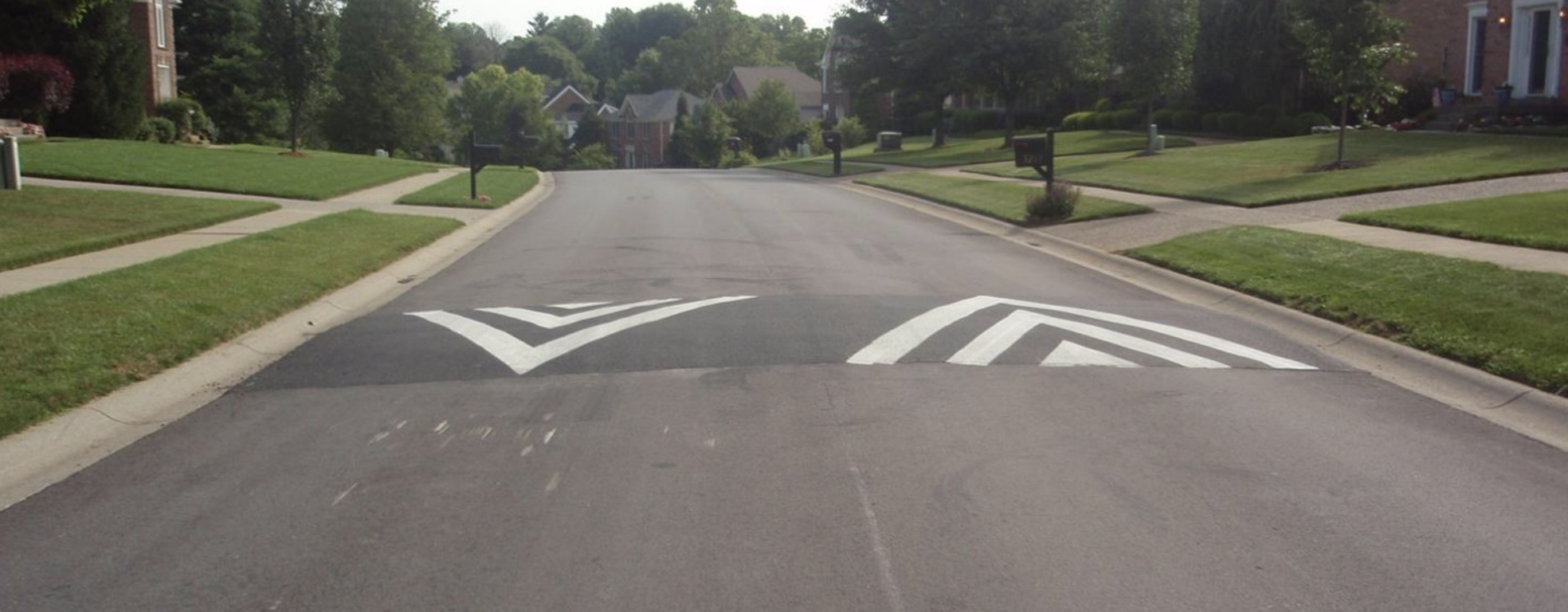
Image Source: Louisville Metro Public Works
DEFINITION AND DESCRIPTION
A speed hump is an elongated mound in the roadway pavement surface that extends across the travel way perpendicular to the traffic flow. A speed hump discourages speeding by producing discomfort if a motorist exceeds the design speed while driving over it.
Five field studies of 51 speed humps measured crash reductions between 33% and 48%. Seven field studies of 199 speed humps measured speed reductions between 6 mph and 13 mph for 85th percentile speeds (FHWA, Engineering Speed Management Countermeasures: A Desktop Reference of Potential Effectiveness in Reducing Crashes, July 2014).
Implementation Categories
| Area(s) | Design and Geometrics, HSIP, Operations & Maintenance |
| Safety Category | 2 |
CONSIDERATIONS
- Do not install on sharp curves; ITE Guidelines for the Design and Application of Speed Humps recommends a minimum horizontal curve radius of 300 feet.
- Do not install near an intersection.
- Generally, not appropriate for transit routes or primary emergency vehicle routes.
- ITE Guidelines for the Design and Application of Speed Humps recommends their use only on streets with a grade of 8% or less.
- On roadways without curbing, delineator posts or signs may be used to discourage motorists from driving around the hump.
- Speed humps can be used on roadways with bicycle lanes.
- Speed cushions are similar to speed humps, but they have cut outs to enable a vehicle with a wide track (e.g., a large emergency vehicle, some trucks, some buses) to pass though the feature without vertical deflection.
- Snowplows can drive over speed humps.
- Speed humps may be constructed using asphalt, concrete, or prefabricated rubber.
- Coordinate with local officials and stakeholders.
APPLICATION
- May be an option on local residential streets and streets providing access to a school or park. The posted speed limit should be ≤ 30 mph and traffic volumes should be relatively low.
- A speed hump typically measures 3 inches high and 12 feet in length along the vehicle travel path axis.
- Install speed humps at least 1 foot from curb or 6 inches from non-curbed road for drainage.
- Install a sign upstream of the speed hump that warns drivers of its presence. (MUTCD W17-1). See Sections 29 and 3B.30 of the MUTCD for information on using markings at and in advance of speed humps. The speed hump sign should be supplemented with an Advisory Speed plaque (see Section 2C.46 of the MUTCD).
- ITE Guidelines for the Design and Application of Speed Humps recommends spacing of 260 feet – 500 feet to maintain an 85th percentile operating speed of 25 mph – 30 mph. Spacing can be adjusted to achieve speeds closer to the target speed.
example
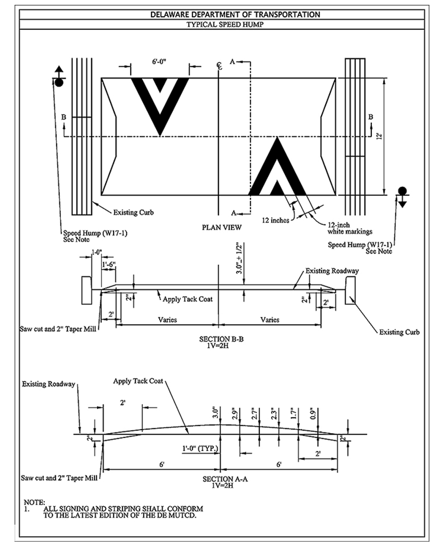
Image Source: Delaware DOT
complementary SSA Strategies
REFERENCES AND RESOURCES
Federal Highway Administration. Manual on Uniform Traffic Control Devices for Streets and Highways (MUTCD), Federal Highway Administration, U.S. Department of Transportation, Washington DC, 2023. https://mutcd.fhwa.dot.gov/kno_11th_Edition.htm
FHWA, Engineering Speed Management Countermeasures: A Desktop Reference of Potential Effectiveness in Reducing Crashes, July 2014. https://highways.dot.gov/safety/speed-management/engineering-speed-management-countermeasures-desktop-reference-potential
Institute of Transportation Engineers. A Guide to Vertical Deflection Speed Reduction Techniques: Planning and Design of Speed Humps, Speed Tables and Other Related Measures, December 2022. https://www.ite.org/technical-resources/topics/traffic-engineering/guide-to-vertical-deflection-speed-reduction-techniques/
CONTACT:
Jill Asher
Research Engineer
jill.asher@uky.edu
Raised Intersections
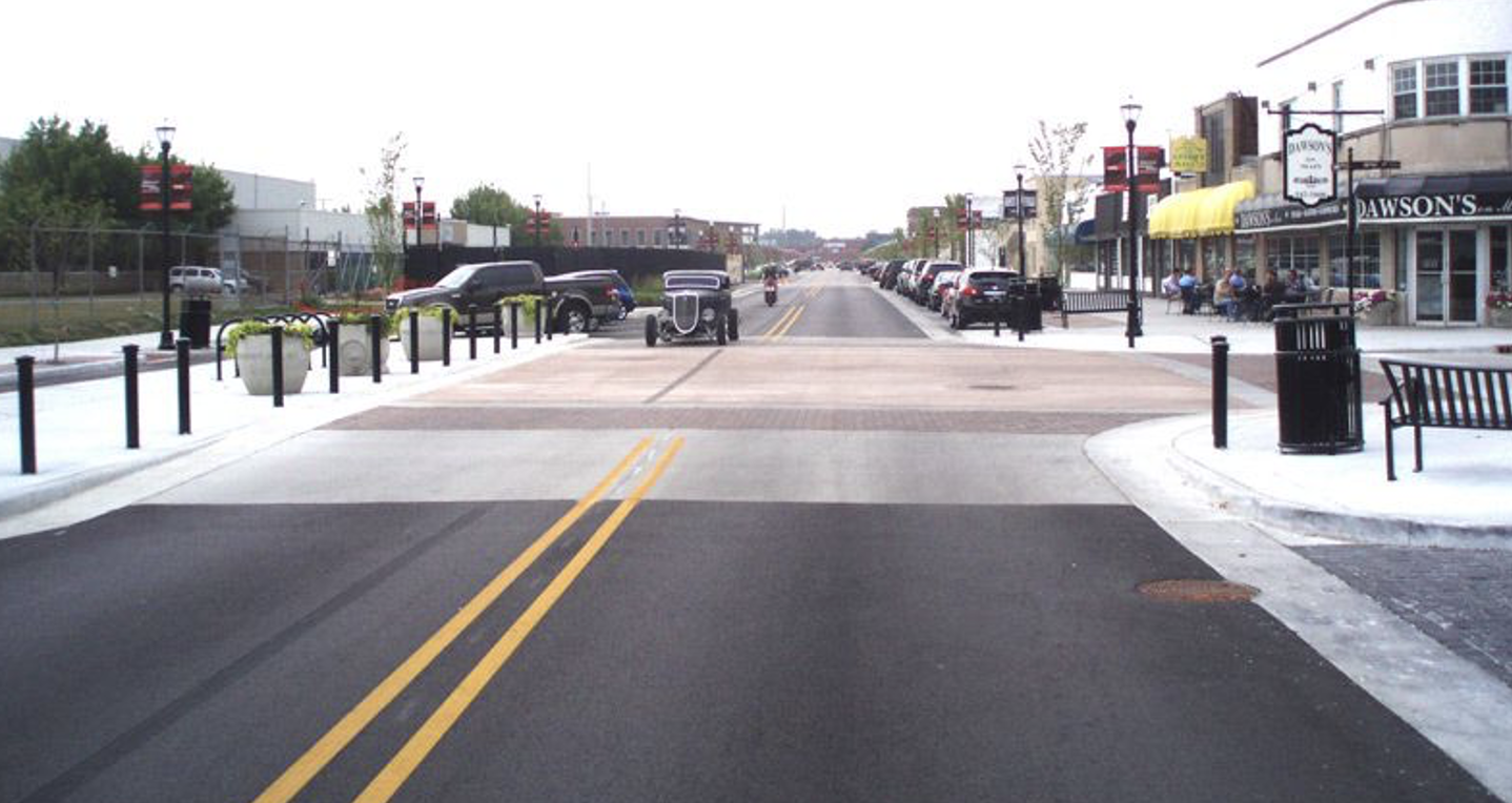
Image Source: NACTO
DEFINITION AND DESCRIPTION
A raised intersection functions like a speed table but extends across the full width of the intersection.. Ramps are installed on each approach, and the intersection elevation is flush with the sidewalk’s elevation. Raised intersections encourage motorists to slow down and yield to pedestrians.
Implementation Categories
| Area(s) | Design and Geometrics, HSIP, Operations & Maintenance |
| Safety Category | 2 |

CONSIDERATIONS
- Do not use at intersections with steep grades.
- Curb ramps must comply with PROWAG and include detectable warning surfaces for visually impaired users at crossings.
- Design to accommodate drainage.
APPLICATION
- May be considered at intersections with high pedestrian activity.
- Elevate the intersection upstream of the pedestrian crossing. The intersection is typically raised to match the sidewalk elevation, with transition slopes ranging from approximately 12:1 to 25:1.
- Install appropriate pavement markings. See Chapter 3B in the MUTCD for details.
- Add bollards to intersections corners to deter motorists from driving onto sidewalks.
example
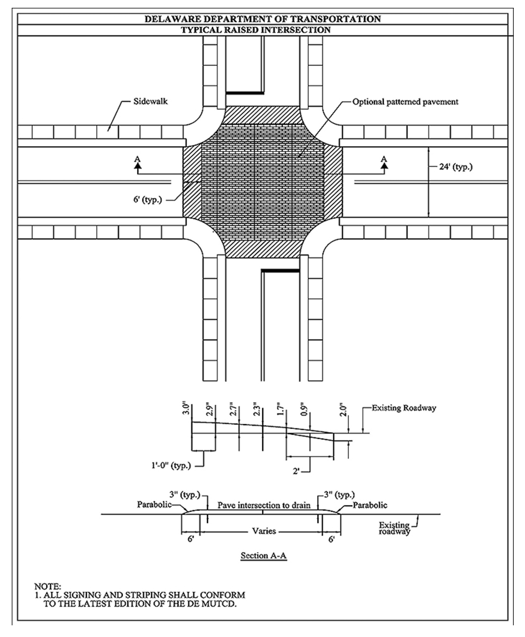
Image Source: Delaware Department of Transportation
complementary SSA Strategies
REFERENCES AND RESOURCES
(FHWA. Traffic Calming ePrimer, Module 3.15. Federal Highway Administration, U.S. Department of Transportation, Washington DC, 2023. https://highways.dot.gov/safety/speed-management/traffic-calming-eprimer
National Association of City Transportation Officials (NACTO). https://nacto.org/publication/urban-street-design-guide/intersections/minor-intersections/raised-intersections/
CONTACT:
Jill Asher
Research Engineer
jill.asher@uky.edu
Using Traffic Signal Timing to Meet Target Speeds

DEFINITION AND DESCRIPTION
Conventional traffic calming techniques are not usually applicable for controlling speeds on urban and suburban arterials. Due to the presence of vulnerable road users on these facilities, speed management is important, but enforcement is difficult to accomplish using traditional methods. On corridors with traffic signal systems, case studies show that is possible to substantially reduce speeding opportunities with little or no impacts to vehicle delays by reducing cycle length and progression speed and dividing the arterial into smaller “coordination zones” (Furth et.al., 2018).
Implementation Categories
| Area(s) | TSMO |
| Safety Category | 2 |

CONSIDERATIONS
- Can be applied on urban and suburban arterials.
- Shorter cycle lengths can reduce pedestrian wait times and encourage pedestrians to cross during the pedestrian walk interval.
- Reducing cycle length from 100 seconds to 80 seconds reduces speeding opportunities up to 28% without any change in vehicle delay (and with a 23% decrease in pedestrian delay) (Furth, 2018).
APPLICATION
- Assess shortening signal cycle lengths and smaller coordination zones for signal systems.
- Use target speeds as progression speeds for the signal system.
example
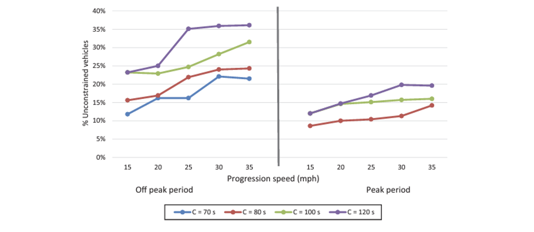
Image Source: (Furth et.al., 2018)
complementary SSA Strategies
REFERENCES AND RESOURCES
Furth P., Halawani A. T., Li J., Hu W., and Cesme B. Using Traffic Signal Control to Limit Speeding Opportunities on Bidirectional Urban Arterials. (2018). Transportation Research Record: Journal of the Transportation Research Board, 2018. 2672: 107-116. https://trid.trb.org/View/1496118
CONTACT:
Jill Asher
Research Engineer
jill.asher@uky.edu
Two-Way Left Turn Lane (TWLTL) Restrictions
DEFINITION AND DESCRIPTION
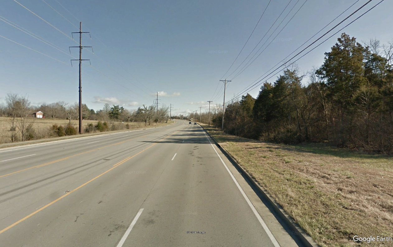
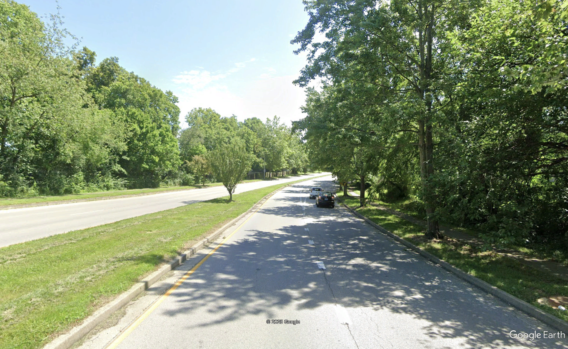
Two-way left-turn lanes (TWLTLs) enhance safety and traffic flow at locations with moderate traffic volumes and moderate to high access point densities. They are typically installed when access densities increase to the point where providing exclusive left-turn lanes with sufficient deceleration space and storage length is impractical without establishing conflicts with adjacent access points. On roadways that already have a TWLTL and few or no access points, a non-traversable median in the center lane can discourage motorists from passing in the turn lane.
Implementation Categories
| Area(s) | Design and Geometrics |
| Safety Category | 1 |
CONSIDERATIONS
- Configurations include raised, depressed, or flush medians. Raised or depressed medians are more effective but also more expensive.
- If raised medians are installed, consider drainage on superelevated sections.
APPLICATION
- On roadway segments where the deceleration and storage length of left-turn lanes does not interfere with other access points, left-turn bays are an option. They can be constructed using curbing or achieved through restriping the TWLTL.
- Depressed, raised, or flush medians may be installed where left-turn movements are not needed or if they are accommodated elsewhere.
- On flush medians double yellow lines and rumble strips may be applied. Flexible delineator posts may be considered intermittently to discourage use of a flush median.
example
Source: Google Earth, Lexington, KY
complementary SSA Strategies
- Buffered Centerlines
- Median and Pedestrian Refuge Island
- Positive Offset Turn Lanes
REFERENCES AND RESOURCES
KYTC Highway Design Manual. 2017. HD-702.10.6 and HD-902.20.
CONTACT:
Jill Asher
Research Engineer
jill.asher@uky.edu
Transverse Pavement Rumbles
Source: Google Earth, Frankfort, KY
DEFINITION AND DESCRIPTION
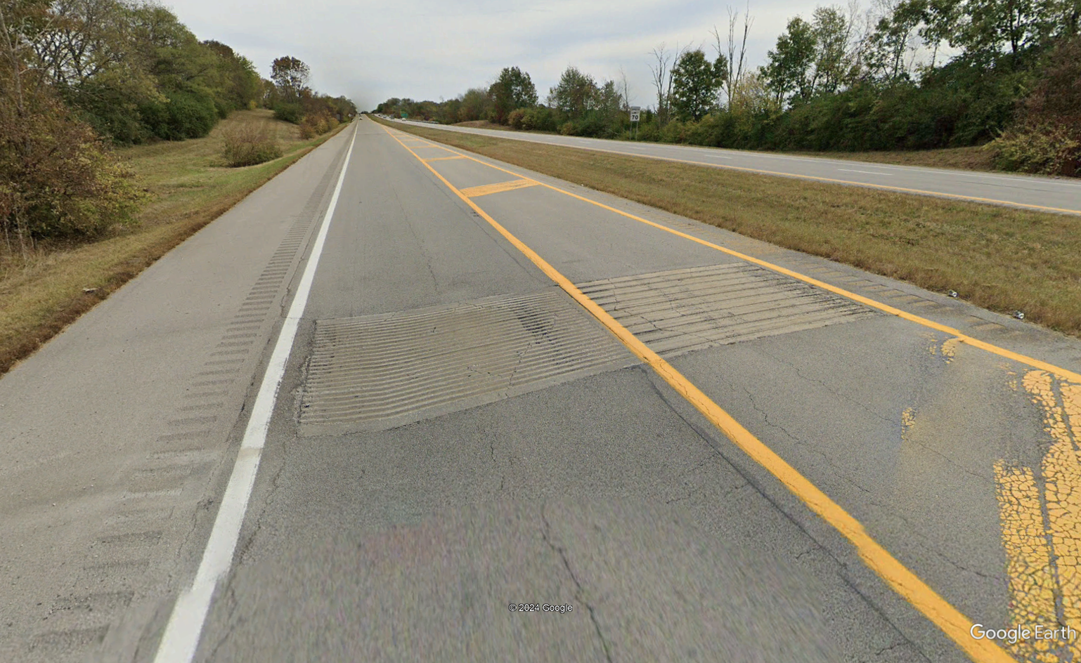
Transverse rumble strips are placed in travel lanes perpendicular to the direction of travel. The noise tires make when they contact the rumbles alert motorists to slow down. They are typically located on approaches to intersections, horizontal curves, work zones, and the ends of freeways.
Implementation Categories
| Area(s) | Design and Geometrics, Traffic Operations and Operations & Maintenance |
| Safety Category | 4 |
CONSIDERATIONS
- Where turn lanes are not needed for operational purposes, a TWLTL may be reconfigured to incorporate raised, depressed, or flush medians.
- See MUTCD Section 3K.02 for more information on transverse rumble strip markings. The MUTCD does not include guidance on the design or placement of the transverse rumble strips. See Traffic Operations Guidance Manual TO-801 for additional information, including guidance on the design and placement of transverse rumble strips.
- Can be used to address roadway departures and right-angle crashes caused by motorists not being aware of an intersection.
- May be thermoplastic or milled in. Typically, rumble strips are extruded or preformed thermoplastic.
- KYTC District Offices can install transverse pavement rumble in a temporary manner. Permanent applications require the approval of the Division of Traffic.
- They can lower crash numbers 28% – 35% (FHWA).
- Motorists may make unusual maneuvers to avoid transverse rumble strips.
- Do not use in curves or within the stopping distance for actual stop conditions.
- Studies have found no statistically significant difference in performance of sinusoidal mumble strips compared to rectangular rumble strips.
APPLICATION
- May be applied to warn of stop or near-stop conditions on high-speed roadways and on approaches to horizontal curves or work zones.
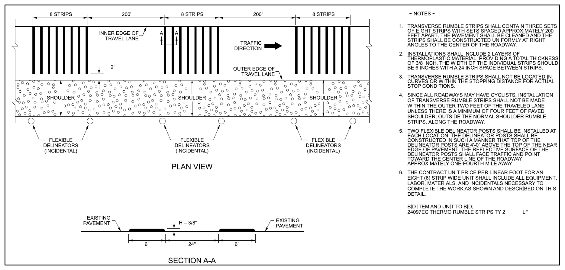
- Installation should consist of three sets of eight strips constructed uniformly at right angles to the center of the roadway with sets spaced approximately 200 feet apart.
- Requirements for different methods of implementation:
- Extruded thermoplastic material — Include 2 layers of thermoplastic material to establish a total thickness of 3/8 inch. Widths of individual strips should be 6 inches with a 24-inch space between strips.
- Preformed thermoplastic material — Follow manufacturer’s recommendations.
- Cut or milled strips (permanent) — Maximum depth of 3/8 inch, width of 7 inches, and spacing of 24 inches between strips.
- Two flexible delineator posts shall be installed at each location. The delineator posts shall be constructed in such a manner that the top of the posts are 4 ft above the top of the near edge of pavement. The reflective surface shall point toward the center line of the roadway approximately ¼ mile away.
- To avoid impacts to bicyclists, do not install strips on the outer 2 feet of the traveled lane unless there is a minimum of 4 feet of paved shoulder, outside the normal shoulder rumble strips, along the roadway.
example
Source: KYTC’s HSIP Project Development Resources – Thermo Rumble Strips Type 2
complementary SSA Strategies
REFERENCES AND RESOURCES
FHWA, Safety Evaluation of Transverse Rumble Strips on Approaches to Stop-Controlled Intersections in Rural Areas. FHWA-HRT-12-047. https://www.fhwa.dot.gov/publications/research/safety/hsis/12047/index.cfm
FHWA, Intersection Safety: A Manual for Local Rural Road Owners. https://highways.dot.gov/safety/local-rural/intersection-safety-manual-local-rural-road-owners/4-countermeasures
KYTC Traffic Operations Manual, TO-801
CONTACT:
Jill Asher
Research Engineer
jill.asher@uky.edu
Superelevation Improvement

Image Source: Google Earth
DEFINITION AND DESCRIPTION
Superelevation promotes motorist comfort as they accelerate a vehicle through a curve. Superelevation may be inadequate due to long-term deterioration from settlement or pavement overlays, or because the roadway was originally constructed prior to common use of superelevation. Superelevation may be inadequate due to design errors, lost over time due to settling, pavement overlays, or mistakes made during the original construction. Curves with inadequate superelevation may increase crash risk. Safety can be enhanced when the superelevation is improved or restored along curves where the actual superelevation is below optimal levels.
Implementation Categories
| Area(s) | Operations & Maintenance, HSIP |
| Safety Category | 1 |
CONSIDERATIONS
- Increasing superelevation to improve motorist comfort may result in higher speeds.
- The slope break between the edge of pavement and the adjacent shoulder should not exceed 8 percent.
- Maintain a sufficient grade along the superelevation transition to provide sufficient drainage where the cross-slope approaches level.
- Improving superelevation is a KYTC SHSP Engineering Strategy.
- Often requires additional right of way.
- Improving superelevation during resurfacing can be a complex process, increasing both project cost and construction time.
- Statewide superelevation data are available.
- Coordinate improvements with curve signing, markings, and other countermeasures for consistency.
APPLICATION
- May be applied on high-speed facility curves that lack adequate superelevation and exhibit poor safety performance.
- Priority should be given to locations with a history of roadway departure crashes.
example

complementary SSA Strategies
REFERENCES AND RESOURCES
AASHTO. A Policy on Geometric Design o Highways and Streets, 7th Edition. Association of State Highway and Transportation Officials, Washington DC, 2018.
FHWA. Low-Cost Treatments for Horizontal Curve Safety 2016. https://highways.dot.gov/safety/rwd/keep-vehicles-road/horizontal-curve/low-cost-treatments-horizontal-curve-safety-2016
KYTC Highway Design Manual, HD-702. https://transportation.ky.gov/Organizational-Resources/Policy%20Manuals%20Library/Highway%20Design.pdf
KYTC Standard Drawings (2025). https://transportation.ky.gov/Highway-Design/Pages/Standard-Drawings.aspx.
CONTACT:
Jill Asher
Research Engineer
jill.asher@uky.edu
Speed Reduction Markings
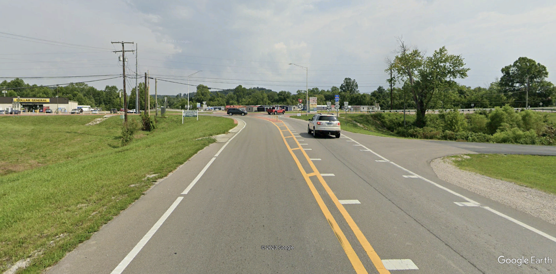
Image Source: Google Earth
DEFINITION AND DESCRIPTION
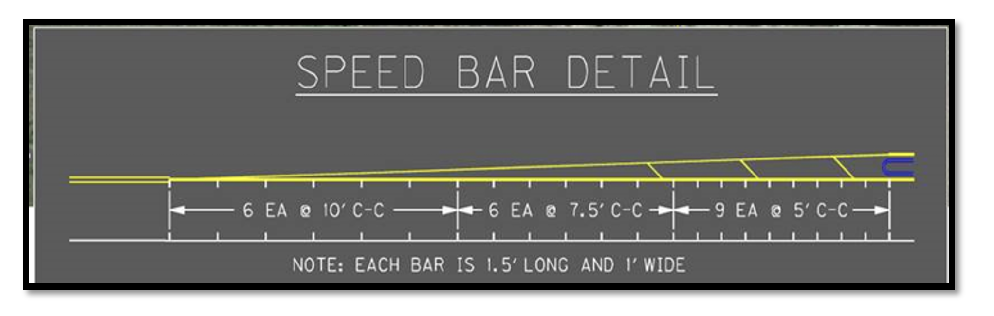
Speed Reduction Markings, or optical speed bars (OSBs), are white transverse pavement markings placed on both sides of a lane perpendicular to the centerline, edge line, or lane line with the goal of reducing vehicle operating speeds. The distance between successive bars is reduced progressively to give motorists the impression that their speed is increasing.
Implementation Categories
| Area(s) | Design and Geometrics, HSIP, Traffic Operations, Operations & Maintenance |
| Safety Category | 2, 4 |

CONSIDERATIONS
- Initial and final spacing depends on the approach speed and the desired speed.
- Speed Reduction Markings can be installed using paint or thermoplastic pavement marking materials.
- Use Speed Reduction Markings in areas with a demonstrated need for additional enhancement of speed transition zones, stop conditions, or changes in horizontal alignment.
- Must accompany appropriate warning signs and other traffic control devices.
APPLICATION
- May be installed at horizontal curves, speed transition zones, and TWSC and AWSC intersections to supplement warning signs or traffic control devices.
- Speed Reduction Markings are 1.5 feet long and 1 foot wide. Consult Section 3B.28 of the MUTCD for guidance.
example
complementary SSA Strategies
REFERENCES AND RESOURCES
Federal Highway Administration. Manual on Uniform Traffic Control Devices for Streets and Highways (MUTCD) Section 3B.28, Federal Highway Administration, U.S. Department of Transportation, Washington DC, 2023. https://mutcd.fhwa.dot.gov/kno_11th_Edition.htm
FHWA, Speed Management: A Manual for Local Rural Road Owners. https://highways.dot.gov/safety/local-rural/speed-management-manual-local-rural-road-owners/3-identifying-countermeasures#:~:text=Optical%20speed%20bars%20are%20used,faster%20than%20their%20true%20speed.
CONTACT:
Jill Asher
Research Engineer
jill.asher@uky.edu
Speed Feedback and Changeable Message Signs

DEFINITION AND DESCRIPTION
Dynamic speed feedback signs contain devices that measure the speed of an approaching vehicle and displays the speed to the vehicle operator. They are used to provide warning to drivers of their speed in relation to either a speed limit (R2-1) sign or a horizontal alignment warning sign assembly with an advisory speed. Sign installations can be permanent or temporary. They are often used in transitions zones that link high-speed to low-speed contexts or on approaches to curves on high-speed roadways to help prevent roadway departure crashes. Installations on two-lane rural horizontal curves are associated with CMFs of 0.93 – 0.95 (Hallmark et al., 2015).
Implementation Categories
| Area(s) | Traffic Operations, TSMO, Construction |
| Safety Category | 2, 4 |
CONSIDERATIONS
- Signs can be mounted permanently on a standard metal pole.
- Must meet applicable MUTCD requirements. See Section 2C.13 for Speed Feedback Signs and Chapter 2L for CMS. Also see Traffic Operations Guidance Manual TO-403-12 for more information.
- Often utilize self-contained power (e.g. solar).
- Requires DSHE approval through the Division of Traffic Operations (except when used in highway work zones).
- Except for installations in highway work zones, Vehicle Speed Feedback signs and plaques shall require the approval of the Deputy State Highway Engineer for Project Delivery and Preservation.
APPLICATION
- Mobile signs may be used for construction and maintenance work zones.
- Mobile or permanent signs may be placed in speed transition zones approaching communities.
- Evaluate using permanent installations at locations with a higher probability of roadway departures (e.g., long tangents before curves with significantly lower design speeds, locations with a history of roadway departures).
- Place signs based on perception-reaction time, deceleration, and expected reduction in speed so the driver has time to react and adjust their speed (see MUTCD Table 2C-3 for minimum advance placement distance). Provide a clear line of sight to signs.
- When used to display the speed of an approaching vehicle in relation to the posted speed limit, the Vehicle Speed Feedback (W13-20aP) plaque shall be mounted below a Speed Limit sign.
- When used to supplement a horizontal alignment warning sign advisory speed, the Vehicle Speed Feedback sign (W13-20) shall be an independent installation near the point of curvature of a horizontal curve.
- The changeable display should not be activated when approach speeds are less than 10 MPH below the speed limit.
- The changeable display may be set to remain blank when the speed of an approaching vehicle is greater than 20 MPH above the posted speed limit to deter drivers from attempting to make the sign display a high number.
- The changeable display showing the speed of the approaching vehicle shall be a yellow luminous legend on a black opaque background. The minimum LED numeral height should be in accordance with the Standard Highway Signs publication.
example

Image Source: MUTCD, 11th Edition
complementary SSA Strategies
REFERENCES AND RESOURCES
Federal Highway Administration. Manual on Uniform Traffic Control Devices for Streets and Highways (MUTCD), Federal Highway Administration, U.S. Department of Transportation, Washington DC, 2023. https://mutcd.fhwa.dot.gov/kno_11th_Edition.htm
Hallmark, S., N. Hawkins, and O. Smadi. “Evaluation of Dynamic Speed Feedback Signs on Curves: A National Demonstration Project.” Report No. FHWA-HRT-14-020. Federal Highway Administration. McLean, Virginia. (January 2015). https://www.fhwa.dot.gov/publications/research/safety/14020/index.cfm
Iowa DOT. Speed Feedback Signs Program. https://iowadot.gov/traffic/Speed-Feedback-Signs
Zineddin, A., Hallmark, s., Smadi, O., & Hawkins, N. Spotlighting Speed Feedback Signs. Public Roads, 2016. https://highways.dot.gov/sites/fhwa.dot.gov/files/FHWA-HRT-16-003.pdf
CONTACT:
Jill Asher
Research Engineer
jill.asher@uky.edu